How to Upload Code of Arduino Pro Mini
Introduction
Today we will take a look at the Arduino Pro Mini, a pocket-size nevertheless powerful member of the Arduino family unit.
Although the Pro Mini is a small device it is quite powerful, as information technology uses the same processor fleck as the Arduino Uno. In fact in some ways information technology is even more than versatile, and it's small form factor and low price makes it platonic for use in permanent projects.
Still programming the Pro Mini is done a bit differently than an Uno, mainly because the Pro Mini has no USB port.
Of course, in that location is a mode around this, and so follow along and come across how the Pro Mini tin be useful for your next Arduino design. And, as a bonus, we will build a battery-powered controller for a small robot arm.
The Arduino Pro Mini
The Arduino Pro Mini was originally developed by SparkFun . Although no longer available from the official Arduino store it is an open-source design and is now manufactured by several different companies. You will accept no problem finding one at a very low price.

Equally its name would imply the Pro Mini is a very tiny device, it'southward not much bigger than the DIP version of the ATMega328 scrap. The Pro Mini uses a surface-mount ATMega328, giving it the full power of the Arduino Uno in a much smaller package.
In fact, in many ways, the Pro Mini is even more versatile than the Uno.
Arduino Pro Mini Pinout
One way in which it is more than capable than the Uno is that about Pro Mini designs have two additional analog input ports, which can likewise double as extra digital I/O pins. This is due to the surface-mountain version of the processor having more leads than the DIP version that the Uno is based upon.

Another way that the Pro Mini outshines its bigger brother is that information technology is available in both a 5-volt and 3.3-volt model. This opens up the possibility of creating bombardment powered projects, or straight interfacing with iii.three-volt logic devices.
The iii.3-volt Pro Mini runs at a slower clock speed, 8 MHz. For most applications, this volition non exist an issue.
Simply for all its extra versatility the Pro Mini has one characteristic lacking – it has no USB port.
While this may seem like a major drawback it isn't really, in many Arduino projects the USB port is merely used for programming and debugging. Once that is washed with the USB port just sits there, taking upwards both space and consuming some electric current.
To program and debug a Pro Mini y'all will utilise an external device, called an FTDI Adapter.
Using the FTDI Adapter
FTDI is an abbreviation for semiconductor manufacturer Future Engineering Devices International . In add-on to interface chips, the company also manufactures a broad range of video adapter and other integrated circuits.
The adapters we are interested in are produced by several manufacturers and are used to interface USB or serial ports to microcontrollers. They are easily obtained on eBay or Amazon, as well as most well-stocked electronics stores.
FTDI adapters come in several shapes and sizes, all of them will have a USB (usually Mini USB) port and a 6-pin connector to adhere to the Pro Mini.
FTDI Voltage Select
The FTDI adapter not only provides a USB port to allow y'all to communicate with the Pro Mini, it likewise supplies power.

Because the Pro Mini is available in both 3.3-volt and v-volt models it is critical that y'all requite it the correct supply voltage. The FTDI adapter will have a method of selecting the right supply voltage, this is usually in the course of a jumper, a switch or a trace on the circuit board that needs to be cut or jumpered.
Make sure you get the voltage setting correct, applying 5-volts to a iii.three-volt Pro Mini can impairment or destroy it!
Connecting the FTDI to the Pro Mini
Your FTDI adapter will have a connector, unremarkably a 6-pivot male header, to attach to the Pro Mini. In virtually cases you lot can simply straight attach it, even so one important thing to note is that this connector (and the connector on the hPro Mini) is not e'er mounted the aforementioned side up.
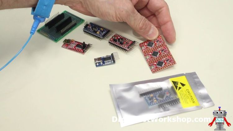
In the above image, I show a couple of Arduino Pro Minis and 2 FTDI adapters. The connector on the blueish Pro Mini (the 5-volt ane) is reversed from the connector on the red Pro Mini (the 3.3-volt ane).
The 2 FTDI adapters also wired backward from each other!
The connections on the FTDI adapter for the Pro Mini are every bit follows:
- DTR – Data Last Fix, a command bespeak sent to the Pro Mini from the FTDI adapter to let it know that it is gear up to ship information.
- TX – Transmit, the betoken sent out from the FTDI adapter.
- RX – Receive, the line that receives data from the Pro Mini.
- VCC – The Power supply voltage, either 3.3 or 5 volts DC.
- CTS – Clear To Send, a control point sent back from the Pro Mini to allow the FTDI adapter know information technology can ship data.
To connect the FTDI adapter to the Pro Mini you lot need to friction match the signals up as follows:

Annotation that the Transmit and Receive lines are crossed between the 2 devices, which makes perfect sense if you think virtually it.
You volition besides notation that the CTS input to the FTDI adapter is grounded, or held at a digital Low. This essentially tells the adapter that it is always clear to transport data. The Pro Mini will take an extra pivot that is grounded for this purpose.
Apply the diagram to a higher place and check the labels on the connectors for both your FTDI adapter and Pro Mini and yous should have no problem connecting the two devices to each other.
Programming the Pro Mini
Afterward yous connect your FTDI adapter and Pro Mini together it's time to programme it.
Virtually FTDI adapters use a mini USB (not micro USB) connector, so y'all volition need to ensure that you accept the correct type of cable. The mini USB cables are not equally pop as they used to be but they are still used for many cameras and microphones.
Connect the other end of the cablevision to your computer. If your calculator is a Linux or Mac then you are ready to go.
For some Windows users yous may need to install drivers to get your FTDI adapter recognized by your calculator.
Arduino IDE Settings
Programming the Pro Mini is no different than programming an Arduino Uno, however, you practice demand to setup your Arduino IDE for the correct type of board and processor first.
Hither is how you do it:
- Open your Arduino IDE.
- Select the Tools carte du jour item from the top menu.
- Go downwards to the Board menu item in the Tools carte. A sub-carte will open, list a big number of Arduino compatible boards.
- Select Arduino Pro or Pro Mini from the sub-carte du jour. The Tools menu will close after y'all make your selection.
- Open up the Tools menu over again. You should now see an additional menu item called Processor .
- Select Processor . A sub-bill of fare will open up, list different Pro Mini configurations.
- Select the correct processor (usually ATMega328P) and voltage/clock frequency to match your Arduino Pro Mini.
- Make sure you have as well selected the correct Port , the 1 attached to your FTDI adapter.
Your Arduino IDE is now gear up to utilize with the Arduino Pro Mini.
You may at present use your sketch with the Pro Mini. All of the example sketches, such equally Blink, should piece of work without modification.
Robot Arm Controller
As an case of using the iii.three-volt Pro Mini, I have created a very unproblematic robot arm controller, meant to be used with the MeArm robotic arm.
If you lot are non familiar with the MeArm y'all can read about constructing it. You can also employ this controller with any arm that has four servo motors, or expand upon it.
The real purpose of this hookup and sketch is to bear witness yous how to use a 3.3-volt Arduino Pro Mini. I'll be the starting time to acknowledge that the controller is very basic, one mean solar day soon I'll show you a much more capable controller.
Controller Hookup
The hookup for the robot arm controller is shown beneath:

The interesting things virtually this hookup is how the reference voltage for the analog inputs is established.
The potentiometers are hooked up to provide a variable voltage to four of the analog inputs. On a 3.iii-volt Pro Mini this voltage should vary between basis and 3.3-volts. A higher voltage would overflow the analog to digital converter in the Pro Mini and could also possibly harm it.
Our power supply, however, is 6-volts. This can be provided past either a demote supply or batteries. A 6-volt supply is ideal for the servo motors, but information technology is too high to use for the analog reference voltage.
The Arduino Pro Mini is powered using the six-volt supply connected to its RAW voltage input. This employs the congenital-in linear voltage regulator on the Pro Mini to derive the 3.iii-volts information technology requires.
When the RAW voltage input is used the VCC pin on the Pro Mini at present becomes an output, instead of being a voltage input. The output is 3.3-volts from the internal regulator.
This is the voltage used as a reference for the analog to digital converters.
Controller Sketch
Once you have everything hooked up you'll need to upload the following sketch to get in all work.
| 1 2 iii iv 5 6 seven 8 9 10 eleven 12 13 14 15 16 17 18 19 20 21 22 23 24 25 26 27 28 29 30 31 32 33 34 35 36 37 38 39 40 41 42 43 44 45 46 47 48 49 50 51 52 53 54 55 | /* Robot Arm Control Demo mearm-controller.ino Demonstrate utilise of three.3 volt Arduino Pro Mini Controls 4-DOF Robot Arm with iv potentiometers Powered past 6-volt power source DroneBot Workshop 2019 https://dronebotworkshop.com */ // Include Servo Library #include <Servo.h> // Create 4 servo objexts Servo base , left , right , claw ; // Integers for analog inputs from potentiometers int basePin = A0 ; // Middle Pot Analog Input Pin int leftPin = A1 ; // Left Pot Analog Input Pin int rightPin = A2 ; // Right Pot Analog Input Pin int clawPin = A3 ; // Claw Pot Analog Input Pin int baseValue = 0 ; // Middle Pot Value int leftValue = 0 ; // Left Pot Value int rightValue = 0 ; // Right Pot Value int clawValue = 0 ; // Claw Pot Value void setup ( ) { // Attach servo objects to output pins base . attach ( 9 ) ; left . adhere ( 6 ) ; right . attach ( 5 ) ; claw . attach ( 3 ) ; } void loop ( ) { // Read the Pot Values // Convert to values between 0 and 180 for the servos baseValue = map ( analogRead ( basePin ) , 0 , 1023 , 0 , 180 ) ; leftValue = map ( analogRead ( leftPin ) , 0 , 1023 , 0 , 180 ) ; rightValue = map ( analogRead ( rightPin ) , 0 , 1023 , 0 , 180 ) ; clawValue = map ( analogRead ( clawPin ) , 0 , 1023 , 0 , 180 ) ; // Write values to servos base of operations . write ( baseValue ) ; // Base of operations servo position left . write ( leftValue ) ; // Left servo position correct . write ( rightValue ) ; // Right servo position claw . write ( clawValue ) ; // Hook servo position delay ( 400 ) ; // Brusque Delay } |
The sketch is very bones. It uses the Arduino Servo Library , which is included in the Arduino IDE.
Four servo objects are declared, i for each of the servo motors. They are named base , left , right and claw to represent the function of each motor in the MeArm.
Some integers are also defined to represent the analog input pins that the potentiometers are connected to. Integers are likewise divers to correspond the value obtained from each potentiometer, this will be the value used to position the servo motors.
In the Setup the servo objects are attached to the pins used to control the servo motors.
The Loop is very simple. The potentiometer values are read and are converted using the Arduino Map Function to values between 0 and 180, which is what the servo objects demand to position the motors.
The value is then written to each servo. Then, later on a short delay, it is all done again.

Load the sketch to your Pro Mini earlier you plug it into the excursion. Then disconnect the FTDI adapter and plug in the Pro Mini to the breadboard.
Connect a suitable power supply and start controlling your MeArm. If you find it "chatters" or moves erratically attempt increasing the value of the electrolytic capacitor.
With any luck you'll be able to command the arm improve than I could (I'yard a terrible robot arm driver information technology would appear)!
Conclusion
The Arduino Pro Mini lives up to that old aphorism that "adept things come up in small packages". Information technology is a fully capable microcontroller that tin brand use of all of your existing Arduino Uno sketches. Its availability in both 3.3-volt and 5-volt configurations will let you to design small battery-powered projects that yous could not utilize the Uno for. And it is very cheap too.
So give the Pro Mini a endeavour for your next design.
Summary

Article Proper name
Programming the Arduino Pro Mini
Description
Learn about the Arduino Pro Mini, a small Arduino board with big capabilities. You will run across how to use an external FTDI adapter to programme the Pro Mini. We will also build a bombardment-powered robot arm controller.
Author
DroneBot Workshop
Publisher Name
DroneBot Workshop
Publisher Logo

Source: https://dronebotworkshop.com/arduino-pro-mini/
0 Response to "How to Upload Code of Arduino Pro Mini"
Postar um comentário